Knowledge base
What is a 3D design model?
A design model turns your drawings into a digital surface that an excavator, grader or dozer can work to. What it is, how the machine uses it and why it is not the same as the existing ground.
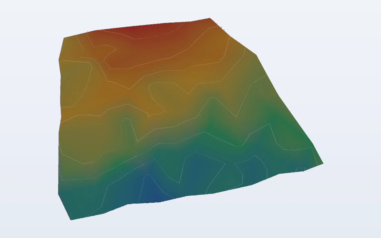
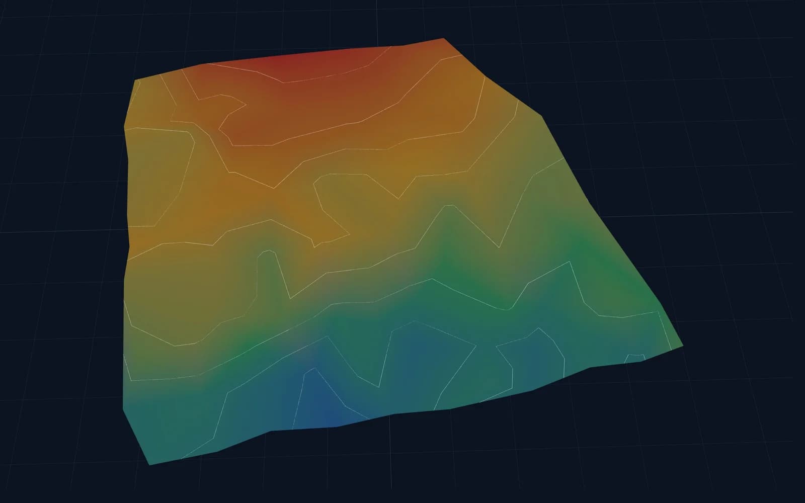
From drawing to surface
A set of construction drawings usually consists of a layout plan, a long section and a series of cross sections. That is enough for a person to understand the design, but a machine control system needs something different: a continuous surface on which a design level is known for every point in the working area.
That surface is called the design model or design surface. It is built as a TIN (Triangulated Irregular Network): a mesh of adjoining triangles in which every vertex has exact X, Y and Z coordinates. Levels between vertices are interpolated linearly, so the machine can read a value anywhere.
A good model also includes linework: centrelines, edges, kerbs, toes and tops of slopes. This linework helps the operator find their way and partly determines how the triangles are formed.
How the machine uses the model
A machine with 3D control knows its own position and that of its working tool, such as the bucket’s cutting edge or the blade, through GNSS receivers (or a total station). The system continuously compares the level of that tool with the design level in the model at the same location.
The difference is shown on the in-cab display as ‘cut’ or ‘fill’, usually with a value in centimetres. With semi-automatic systems the hydraulics adjust the blade or bucket on their own. Digging, grading and finishing can then be done without pegs or repeated setting out.
The machine follows the model literally. Any error in the model, however small, is therefore built literally as well. The quality of the model matters as much as the quality of the machine.
Design versus existing ground
It is important to keep two surfaces apart. The existing ground (the survey of the current situation) describes the site as it is today. The design surface describes what it must look like after the works.
The machine always works to the design. The existing ground is used to determine where the design ties in with its surroundings, where slopes end and how much material must be cut or filled. Without a reliable survey of the existing situation, a design can look right on paper and still tie in oddly on site.
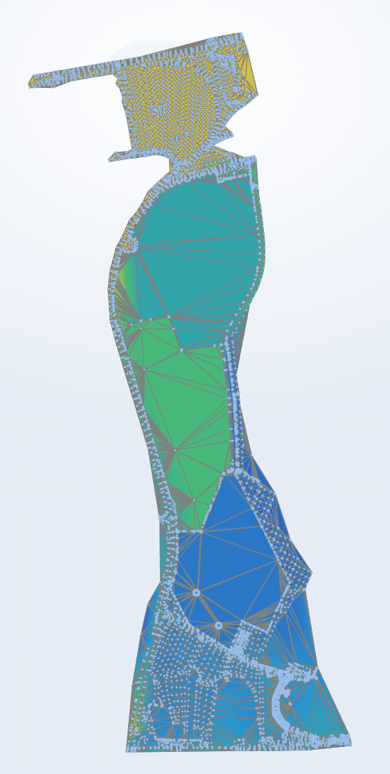
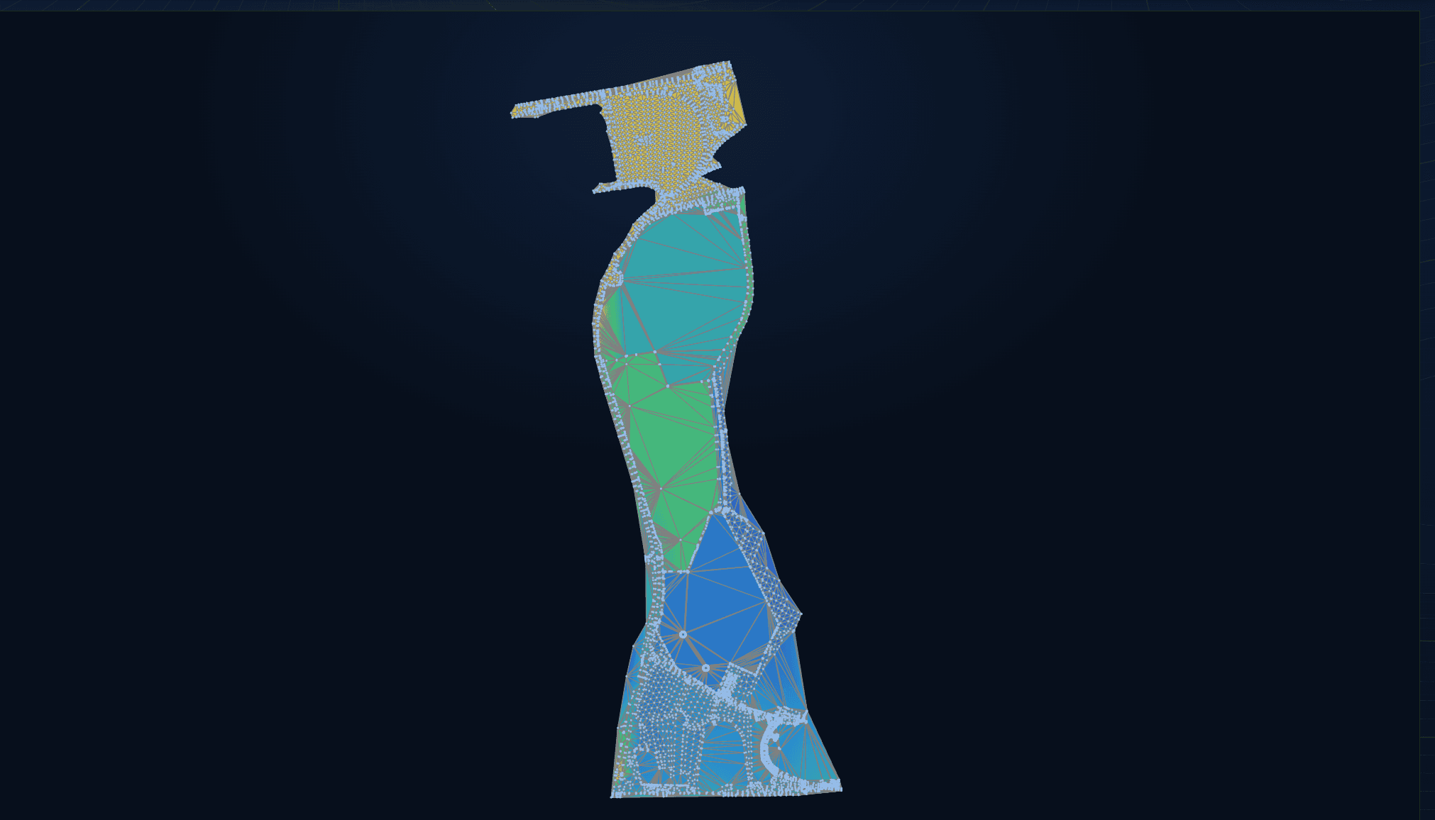
Several layers in one project
A road project or excavation rarely has a single design level. Several surfaces are often produced, each for a stage of the works:
- formation level or bottom of excavation;
- top of sub-base or base course;
- finished level (for example underside of surfacing);
- slopes, ditches and tie-ins with the existing ground.