Knowledge base
Linework and breaklines
Breaklines define where the surface changes direction. Without correct breaklines, the triangle mesh cuts straight through kerbs and slope edges. Why linework matters so much, both for the model and for the operator.
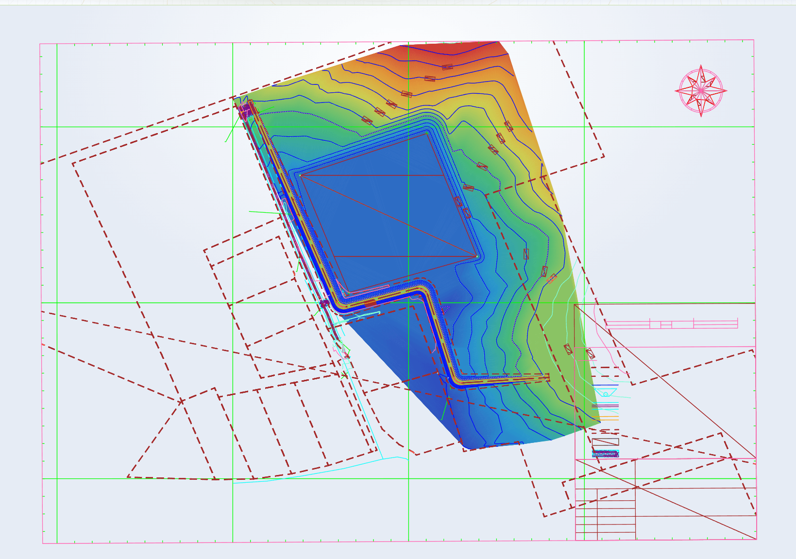
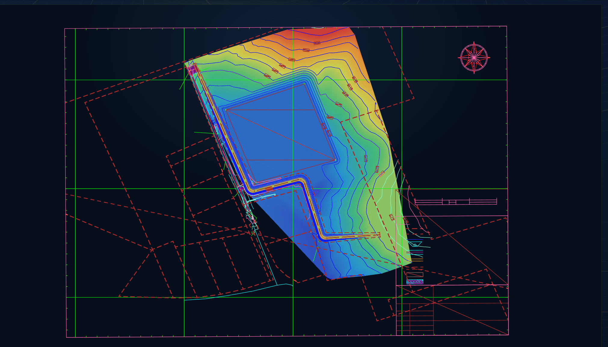
What is a breakline?
A breakline is a 3D line along a place where the slope of the surface changes abruptly: the edge of a carriageway, the toe or top of a slope, the invert of a ditch, the top of a kerb.
When a TIN is built, triangles are formed between the available points. Without breaklines, the software decides on its own which points to connect, and that may run straight across an edge. A breakline forces the triangle edges to follow that line, so the change in grade ends up in exactly the right place.
Typical linework in a design
Road and drainage projects keep using the same kinds of lines. Each of them has a role in the model or on the machine display:
- centreline: reference for chainage, cross sections and offset;
- edges of surfacing and sub-base;
- kerbs and channels, ideally with their own levels;
- toe and top of slope;
- ditch invert and ditch edges;
- tie-in line with the existing ground (daylight line).
Why linework determines quality
A model without breaklines, or with incomplete ones, can look fine from a distance and still contain errors in detail: a carriageway that sags slightly between two sections, a slope that flattens too early, a ditch that rises where it should not.
A common cause is linework drawn in 2D only. A line without a level, or at level zero, pulls the surface down or is ignored. During modelling, every relevant line is therefore brought to the correct level, from the sections, the spot levels on the plan or the adjoining surfaces.
Crossing lines with different levels also need attention. Two breaklines that assign a different level to the same point create a conflict that has to be resolved first.
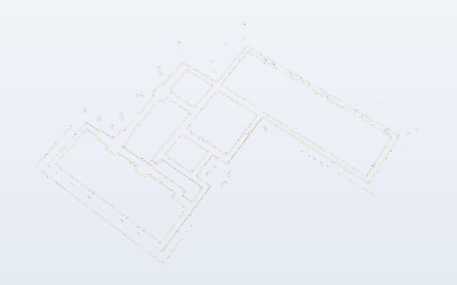
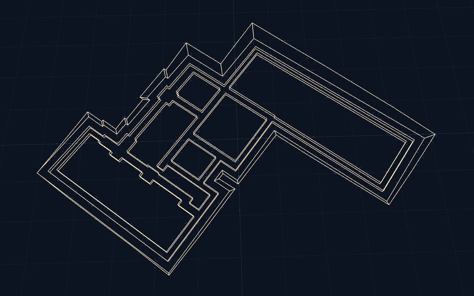
Linework for the operator
Besides its role in the model, linework has a practical function in the cab. The operator sees their position relative to the centreline, the edge of the surfacing or the edge of the excavation. Many systems can also guide to a line, for instance to dig a ditch along a fixed alignment or hold a given offset.
Clear linework, logically split into well-named layers, makes work in the machine easier. Too much detail (text labels, hatching, dimensions) clutters the display and is therefore left out.